 This
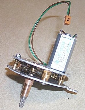
is a completed "Gear Motor". You can see how long the output shaft is and
that it is splined on the end.
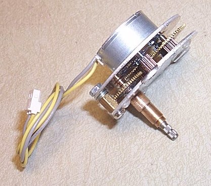
This
is a completed "Gear Motor". You can see how long the output shaft is and
that it is splined on the end.
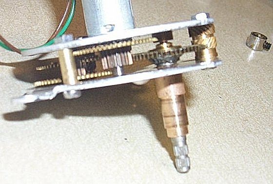 This
shows the soldering required to the output shaft. Look just under the output
gear to see the silvery metal attaching the gear to the shaft. The output
gear has a ratchet and needs to be defeated. I remove the flat spring,
and the ratchet disk. Then file clean spots on the gear and the sides of
the shaft where it is square. Solder it down and set aside to cool down.
Since the shaft in this area is square, it gives it a lot of strength.
This
shows the soldering required to the output shaft. Look just under the output
gear to see the silvery metal attaching the gear to the shaft. The output
gear has a ratchet and needs to be defeated. I remove the flat spring,
and the ratchet disk. Then file clean spots on the gear and the sides of
the shaft where it is square. Solder it down and set aside to cool down.
Since the shaft in this area is square, it gives it a lot of strength.
The first in the gear train is a phenolic gear. The whole gear was removed, the shaft too, to make a place for the motor to mount. Attach the small removed gear to the motor shaft, this requires some machine shop work. Using the gear that comes with the unit helps center the motor shaft correctly. Motor mounting holes are drilled in the top plate to attach the motor.
Additional holes are required to mount the two plates to each other as they are not attached at all. Spacers, 0.3 inch were used for this. In this picture, brass parts were used along with M2-12 screws & nuts.
I cannot stop the shaft, even with only 3.8 volts on the motor! It rotates once in about 3 seconds, or so, depending on the motor used.
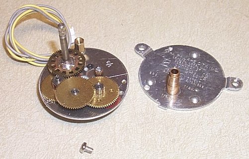
Here you see the gear set exploded, and finished. Actually it needs
one more stand-off to connect the outer plates together. You can also see
the soldering required to the output shaft to defeat the racheting mechanism.
A small flat brass spring has been removed from under the first gear, the
one with the four bumps. It was also part of the rachet mechanism. One
end of that spring was clipped off to continue spacing the first gear away
from the bottom plate.

Here you see the newer gear that would get modified from the older
gear sets. See the gap between upper and lower small gear on the stand-alone
gear. This one gear is OK, but the older sets have teeth from top to bottom
and needs to have this gear gap. This enables this gear to be able to move
to the last post.
Gear Reduction is as follows:
Motor to first: 12-60
First to Second: 16-60
Second to Third: 15-60
Third to output shaft: 20-60
This gives about (5*3.75*4*3) 1:225 (225 motor rotations to give one
output shaft rotation.