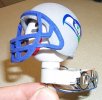
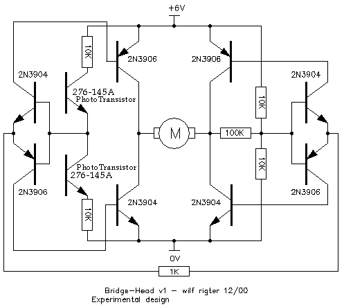
This circuit, Bridge-Head #2. Thanks to Wilf Ritger.


This circuit, Bridge-Head #2. Thanks to Wilf Ritger.
Note: If you choose the kind of LDR that is in a metal transistor type package, rather than the white ceramic type, that is good. If you have the type that is white ceramic, then you do need to cover the back and sides of these LDR's with either heat-shrink or black paint. The reason is that the light goes through the ceramic and affects the LDR, from sides or back. You may want this "feature" depending on what kind of response you want. This modification will increase the sensitivity (maybe). I noticed this because Radio Shack had two of these metal-can type in the last two packs that were purchased. They worked the best of all.
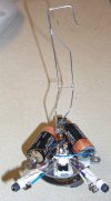
Showing the hanger soldered to a DuBro collar, set screwed to the
gearmotor output shaft.
Photo Transistors work great in daylight or early dusk. Very active!
CDS cells (LDR's) work best in high contrast areas at night, i.e.
dark street with street lights (sodium type).
Having them both in parallel seems to cut the daytime phototransistor
response time.
So, for now the LDR's are unplugged.
Gearmotor shown on another page.
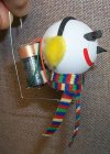
Two surplus Lithium 3-volt batteries for 6-volts total.
The "white stuff" is a stiffener compound, usually used to hold
electronic parts in place, kinda like hotglue. Under that "white stuff"
is the bridge. The sensors are plugged into pin sockets soldered into the
circuit. This allows quick change of different types, to test real-life/circuit
responses. The bridge is double-sticky-foam-taped to the gearmotor, as
are the batteries.
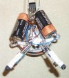
You can see the on/off switch in back.

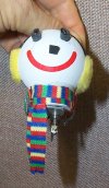
How it looks if it were hanging.
Shows the CDS cells (LDR's) in parallel with the phototransistor/10K-resistor
combo.
Brown & Blue wires are the battery connections.
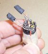
Here's that circuitry. Eight transistors on the top of jack's mini
motor.

