Today this slider got a new controller, 12/19/2001.
This controller is almost exactly the same
as the one on the 16LF84 button above, with no IR sensor.
Hopefully this will eliminate the "legs getting
out of position" syndrome.
After every 100 cycles the legs reposition
themselves, "getting into sync".
Actually this slider does not weigh enough
to keep itself in position when just one leg moves.
A heavier frame will be constructed with the
motors farther apart. Right now the motors are about 4 inches apart
and that's not enough to keep it from tipping. 3/32" Brass rod will
be used and the motors will be about 5" apart. Extra weight may be
added if needed.
Rotational switches:
#10 guitar string is used, cut in about a
1 inch long piece, bent 90 degrees at about 3/4 inch, hot-glued the short
end to the frame so that the long end points down. Soldered this
hot-glued switch wire back to the controller board so that when the leg
comes around, it grounds this "guitar wire" and tells the microcontroller
that it did reach it's correct angle. The slider frame is electrical
ground. On two of the legs, an extra wire is attached so that when
the leg comes around it hits the switch at the correct position.
Power-Up:
Set counter=100.
Locate all three legs to the same rotational
direction, i.e. they all point North, for instance.
Main Loop:
Then each leg rotates individually and a "beep"
sounds. Motor 1 - Beep - Motor 2 - Beep - Motor 3 - Beep.
When all three legs have moved, all three
legs simultaneously rotate the opposite rotation and a "Beep-Beep" sounds.
Counter = counter-1
If counter = 0, Then goto Power-Up:
Else goto Main Loop.
Interrupt: When
the 'edge' detector is activated;
Then a triple "beep-beep-beep" sounds and
all legs relocate to about 60 degrees or so.
Action continues from where it got interrupted.
Uses three vertically mounted Nihon Mini-Motors.
No sensors yet, coming later.
Motors mounted in a "Y" frame with the motors being about 4 inches
away from each other.
Motors are screwed into brass nuts. The brass nuts are soldered to
the frame.
Has legs that are about 1 inch long with 0.55 inch brass domes for
feet
( domes made with a Whitney punch, with the "bump" hammered down, after
punching )
This is so that it will "slide" on a tight napped carpet, and does.
First "sliding", July 10, 2001.
Uses the 1-2-3-MOVE "improved" circuit by Bruce N. Robinson, Thanks
Bruce! http://www3.telus.net/rfws/beam/sldr_01.html
whine-whine-whine-WHINE wav file, see button above. <g>
This moves each leg individually, clockwise 1-2-3, then moves all legs
together, counterclockwise.
Rewired MicroCore, 1.3M resistors, 0.22uF caps, 74HC14 core, 74AC245
driver, no sensors yet.
Since the driver is a single 74AC245 and there's not enough drive for
the common side of all motors,
the counterclockwise movement is less than each individual movement.
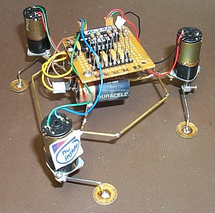
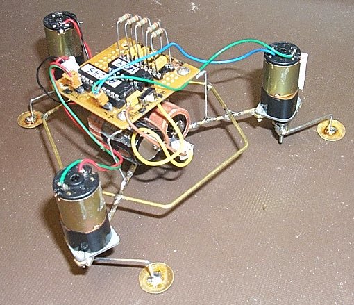

You can see the brass nuts that are soldered to the frame. This is so
that the motors could be removed, later.