PIC-16LF84 = BEAM Walker

My First One
Two Motor WalkerSchematic
This one has a movie1.37MB MPG Movie, 320x200 resolution, 15 seconds..
Nihon Mini Motor Bug
The Gear SetGear Modifying Instructions.
Bridge Head
CyberArm revisited

Symet Page
Turbot Page1.37MB MPG file, first one.1.37MB MPG file, second one.
Biggie Page
Slider Pagewhine-whine-whine-WHINE-WAV file, 76K.
PIC-16LF84 chip, emulates a microcore.Schematic - JPEG image 925 x 683 pixels.Source file for GP16LF84.Hex File for programming into PIC-16LF84-04/P

Pictures

Here is my first attempt to emulate a microcore with a PIC-16LF84/04-PC microcontroller.

It has the following inputs:

1 Feeler. [JP3]
4 Gearmotor rotation limit switches.
    CW and CCW for each motor. Closes to GND. [JP1 & JP2]
1 IR-Module sensor. (marked S28). [JP3]


It has the following outputs: [JP1 & JP2, in schematic]

4 motor driver signal outputs going to 74AC245 motor drivers.
4 LED's for state watching above 4 pins.
1 Pin & LED to the 74AC245 enable line, LED out = '245 off.
1 piezo element or cell phone ear speaker. [JP3]
1 Pin to a BS250 P-ch FET, in the RC clock circuit. 0 = fast, 1 = slow.
    Slow = ~37KHz, Fast = ~61KHz, measured at OSC2/CLKOUT pin.
1 Pin - OSC2/CLKOUT, may later go to an IR-LED driver.


It has the following features:

PNC microcore, with pauses between steps.
Front feeler causes reversing, at a different gait.
    Reversing:
    Front only tips a little while rear moves a lot, for a pre-set # of cycles.
    Goes, lip lop lip lop . . . (the sound it makes when moving in reverse).
        Short cycles the front motor while the rear motor runs full time.
Fast forward upon sensing any IR, for a pre-set # of cycles, just after a quad "chirp".
Occasional pause & flash lights mode. (hiccup 1)
Occasional longer pause between steps. (hiccup 2)
Piezo element for chirps.


Right Side View - JPEG image 1078 x 571 pixels.
Here is the side view.  Shows the feelers, currently without the grounding ring.  Later will be installed a piece of guitar wire (the core of what you see) in a 1/4" circle surrounding the feeler about one inch out from it's base.  This has been already tried and works successfully.  The reason that it isn't there is, that the gearmotor limit switches needed to removed and relocated.
Leg wire ? Oh, yes it's coat-hanger, straightened out! Back legs were stripped of it's coating, front legs not stripped yet. The back legs work great, pushing into the surface of whatever it is walking over.  A slight ramp just ahead of the "pad" (the place where contact is made) helps to crawl over stuff. Front legs have this ramp in both directions for easier reversing.

Left Front Angled View - JPEG image 1063 x 662 pixels.
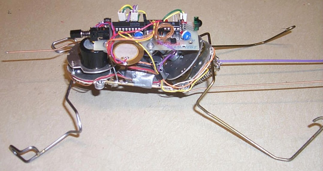
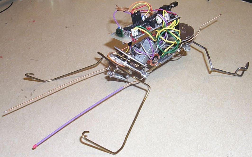
Here is a front angled view.  Shows how steep the front motor is angled back.  Steps kinda high.

Showing Limit Switches - JPEG image 402 x 357 pixels.
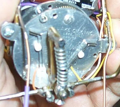
This shows the limit switches on the bottom of each gearmotor.  Some hot melt glue holds them in place.  There's a small pin extending down from the spring assembly to just above the motor plate (see arc scratches in plate) that activates the switches.


Paul T. Barton

This page updated: February/27/2002

Top of page