Number Two Walker (No Name)

My First One
My Second OneSchematic
This one has a movie1.37MB MPG Movie, 320x200 resolution, 15 seconds..
Nihon Mini Motor Bug
The Gear SetGear Modifying Instructions.
Bridge Head


Symet Page
Turbot Page1.37MB MPG file, first one.1.37MB MPG file, second one.
Biggie Page
Slider Pagewhine-whine-whine-WHINE-WAV file, 76K.
PIC-16LF84 chip, emulates a microcore.Schematic - JPEG image 925 x 683 pixels.Source file for GP16LF84.Hex File for programming into PIC-16LF84-04/P


This walker uses rather LARGE gear sets. These were taken from 120 Volt AC gear motors that were marked with "1/3 RPM" that cost $1.00 each at the local surplus store. They require a lot of work to be able to use them. The output shaft needs to have the ratchet mechanism defeated and the end plates do not have any mounts to each other. Both end plates of the gears are aluminum. The motor is mounted where the first phenolic gear shaft was. Some of the gear sets need other mods to get them to work at all. I used DuBro 3/32" collars drilled out with a #29 drill to fit over the output shaft splines. Output shaft is about one inch long. The bug's legs are 3/32" brass rod, recycled from many efforts to get other bugs to walk correctly, hence the "patches" and extra soldering. The two batteries are mounted under the circuit board between the gear sets. Frame rails are 1/8" brass tubing with soldered in paper clip wire loops at the ends to put the motor mounting screws through, whew.

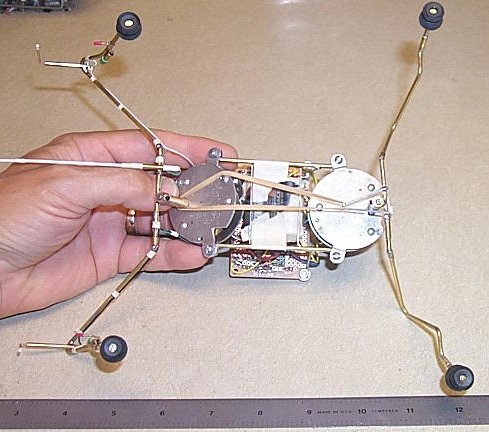
The gear sets are roughly 1:133, this is from a quick tooth count. The front motor rotates about 40 degrees and the rear motor rotates about 50 degrees for the same elapsed time on a microcore. The two motors are different.

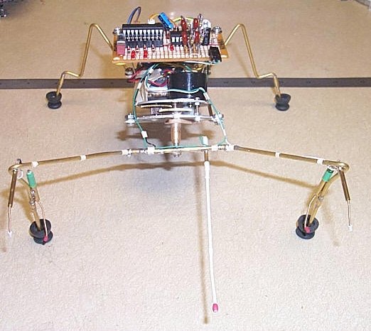
MicroCore is the 74AC14 with the two diodes to keep it in step. The motor driver is a reversing 74AC240 setup. Both circuits are from Wilf Rigter, Thanks Wilf! Timing R/C = 1.75M resistors and 0.1UF caps. The circuit board is from Radio Shack. There are four LED's to show the motor driver activity and another LED to show when the backup circuit is activated.

Whiskers are guitar wire with heat shrink inside of 1/8" brass tubing. When bent, the guitar wire touches the tube, and then the timed backup begins.

Battery is surplus Lithium, 3V each, two batteries. Yes, it does step lively! The neighbor dog, "Lucky Dog" does bark a lot when I am outside testing in the flower beds.

Feet are soldered on brass thumbtack heads and over the tack heads are vibration dampening rubber boots from old hard drives. Since I live in Oregon, I guess that you could call them "galoshes".

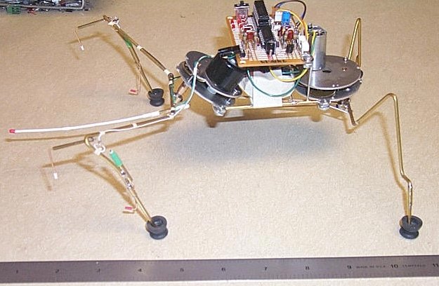
As it walks, it sort of "stomps" it's feet. This does cause problems with the permanently mounted front leg "sensors". Sometimes they trip when a front foot comes down.

A single rubber band keeps the back feet in line.


Click for LARGE picture !Click for LARGE picture !Click for LARGE picture !Click for LARGE picture !

This is the one that got dissassembled to make the PIC-16LF84/04-PC Robot.

Paul T. Barton

This page updated: February/27/2002