Pix #1, Click for larger pix.
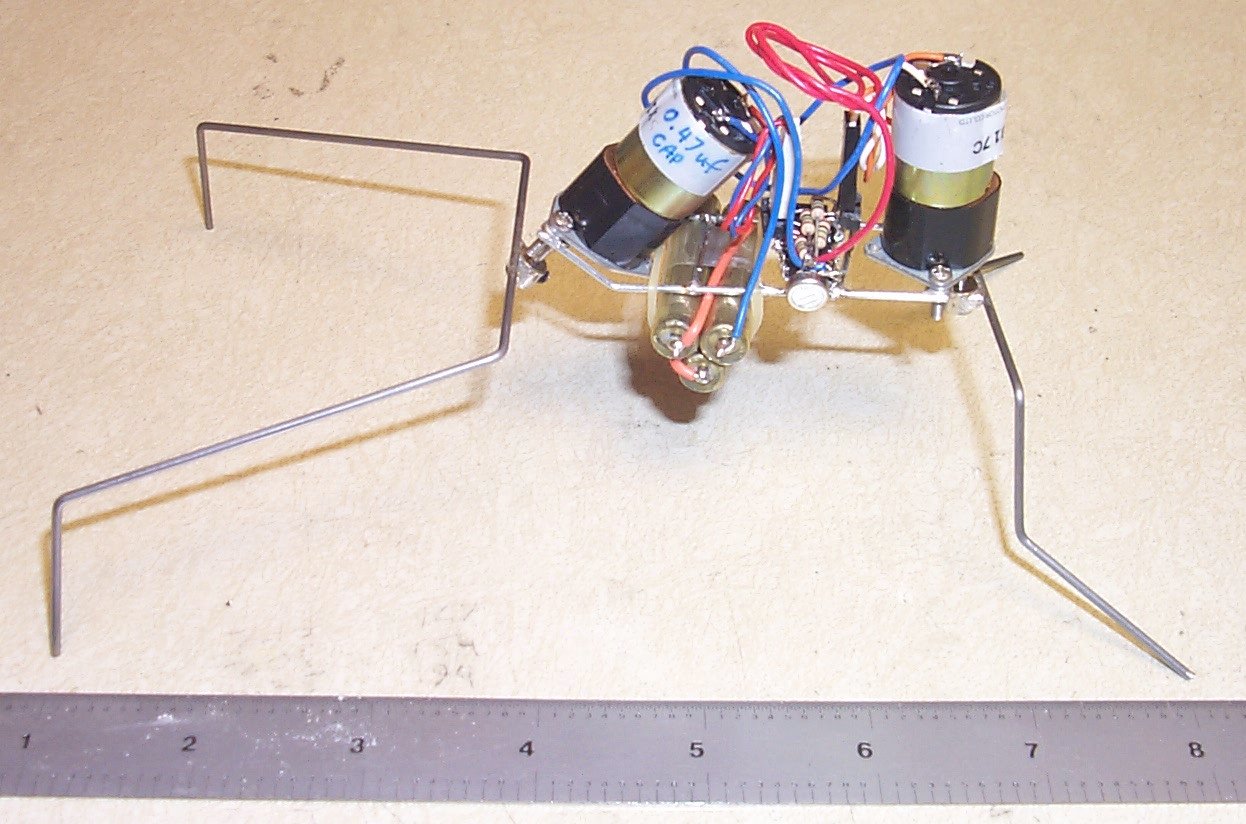 Here
it is. With a ruler to show how it's size. On the other side of this 'bot,
is a single pin on the battery and a socket on the wire. Plugs in for a
pseudo-switch to get it started walking. Frame is formed with Jumbo paper
clips with M2 nuts soldered to the ends where the M2 screws go through
the motor mounts. I did have to open up the holes slightly to get these
screws to go through those motor mount holes. This way I can take it apart
or repair it, without damaging anything. Legs are large piano wire, I don't
suggest this stuff. You need a file to score (deeply!) it before breaking,
then a grinding wheel or stone to clean up the split ends, not a clean
process. I will use brass rod next time. I used DoBro collars, drilled
out to fit the shafts, for the leg mounting. On the front motor you'll
see a note to me, "0.47UF CAPS" these are mounted across the motor terminals
and are 1210 size SMD parts.
Here
it is. With a ruler to show how it's size. On the other side of this 'bot,
is a single pin on the battery and a socket on the wire. Plugs in for a
pseudo-switch to get it started walking. Frame is formed with Jumbo paper
clips with M2 nuts soldered to the ends where the M2 screws go through
the motor mounts. I did have to open up the holes slightly to get these
screws to go through those motor mount holes. This way I can take it apart
or repair it, without damaging anything. Legs are large piano wire, I don't
suggest this stuff. You need a file to score (deeply!) it before breaking,
then a grinding wheel or stone to clean up the split ends, not a clean
process. I will use brass rod next time. I used DoBro collars, drilled
out to fit the shafts, for the leg mounting. On the front motor you'll
see a note to me, "0.47UF CAPS" these are mounted across the motor terminals
and are 1210 size SMD parts.
Since I don't have any "centering" devices on the legs, this unit seems to fall over occasionally. I may have to re-do the back legs' geometry. Any ideas ?
Pix #2, Click for larger pix.
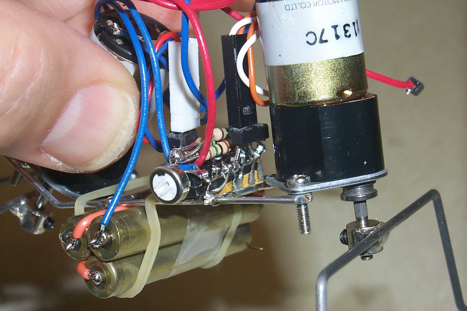 Closeup
of my thumbnail, the freeformed ucore and back legs. 74AC14, 0.22UF caps,
1M resistors, 1M POT for speed, 1N4148 diodes. I mounted the caps on top
of the IC, diodes and resistors on the bottom of the IC. One side of the
POT goes in the ground connection of the resistors would have gone, the
other side of the POT goes to all four resistors connected together. This
POT changes the resistance (increases or decreases) of all four resistors
at the same time. For me, this adjusts the speed of the microcore without
having to "change" resistors, a real pain with freeformed stuff.
Closeup
of my thumbnail, the freeformed ucore and back legs. 74AC14, 0.22UF caps,
1M resistors, 1M POT for speed, 1N4148 diodes. I mounted the caps on top
of the IC, diodes and resistors on the bottom of the IC. One side of the
POT goes in the ground connection of the resistors would have gone, the
other side of the POT goes to all four resistors connected together. This
POT changes the resistance (increases or decreases) of all four resistors
at the same time. For me, this adjusts the speed of the microcore without
having to "change" resistors, a real pain with freeformed stuff.
The motor connections have been shortened and square pins added to the freeformed ucore for quick disconnecting, should such a need arise.
Also, note the three batteries taken out of a 9V alkaline. The red and blue wires are battery connections to the ucore. Note that the blue wire is going to the "last" battery in the stack, meaning GROUND or NEGATIVE. Also note that the button is negative, for these cells. If you choose to use these types of batteries, check the polarity of the cells that you take out, all of them!!!
Batteries held on with a rubber-band. Hey, it works.
The two extra gates in the ucore are currently unused. Maybe they'll become a biasing bicore for turning, since this 'bot doesn't back up. I may use them for a bicore "squeeker".
The microcore goes as follows (my choice)
gate 1, pins 1,2, in out
gate 2, pins 13,12, in out
gate 3, pins 3,4, in out
gate 4, pins 11,10, in out
This way three of the caps just go across the top of IC. The one that
goes to pin 1 and 10 gets soldered to pin 1 with a wire to pin 10. Diodes
were soldered on the bottom of the IC and then the resistors were added.
The common point of the resistors that would have gone to ground, go to
one side of the POT, as shown in Pix #2. The
other side of the POT goes to pin 7 (GROUND) of the IC, or negative battery.