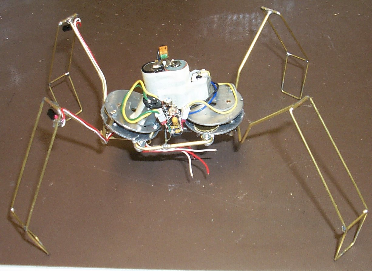
Number 5 Walker


Here's my latest walking bug. I am using a 74HC14 PNC microcore tied
to a 74AC240 motor driver, no reverse.
Head Added !
Shows the bug on top of a briefcase
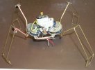
On the desk top
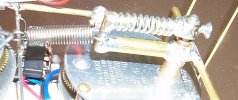
Showing the (output shaft to legs) strain relief mechanism.
The DuBro collar is attached to the motor output shaft and the spring
through the brass tubing.
The lower arm rotates on the motor shaft extended sleeve,
has the legs attached to it and is attached to the other end of the
spring.
The spring (bends and) allows the legs to hit on either side and not
destroy the legs/collar/gears/motor/etc.
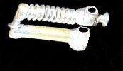
Here is a crude mockup of the above photo edited to show the strain
relief mechanism.
The motor shaft goes through both holes on the right.
The lower hole rides around the extended output shaft bearing.
The upper hole clamps on the output shaft.
Legs are cut off for clarity. (See above pix)
Bottom view showing back leg centering spring.
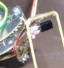
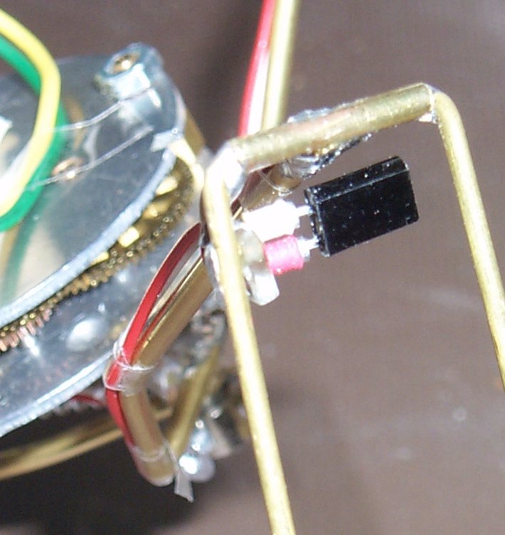
Here's the IR PD (SFH235) mounted in a 2x2 piece of holey board.
Plugged into sockets and wired back to the microcore.
Even though these pictures show loose ended wiring at the other end,
it's now connected.

Going for a walk.
This one seems to try and get it's legs stuck in most anything.
The bottom portion of the legs has been covered with white heat-shrink
tubing to try and defeat the "getting stuck" syndrome.
Also, it tends to bend it's own legs out of shape and needs repairs
often.
New: The lower portion of each leg has been filled in with white "paperclay".
Gives it a little more weight for each foot.
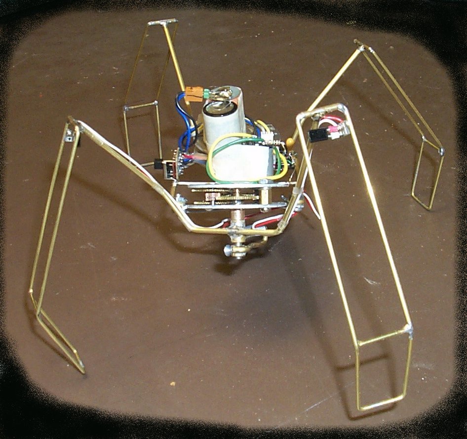
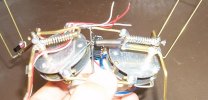
The following pictures courtesy of Dennis Coleman.
The batteries have been moved underneath and a head has been added.
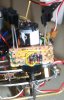
This shows the gearmotor and circuitry, SMD parts.
74AC04 SMD IC, two PD's on long leads,
Circuit is PSH3, by Wilf Rigter, converted to use a 74AC04.
Sorry about the out of focus picture.
This shows the gearmotor alone.
The shaft has had about 1.1" cut off, it was really long.
The nut and screw end, that you see here, is 4-40.
New: Head circuit looks different, acts the same.
Paul T. Barton

Top of Page
This page updated: April/04/2002