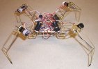
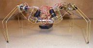
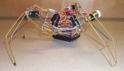
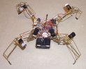
This is a second or third attempt at making
an articulated 4 legged walker, which it now does. (February 27, 2002)
This one is patterned after Tilden's Spyder but has some major differences.
Nihon mini-motors were chosen to use instead of trying to dig up
OTU's and pager motors. In existence is the frame, with all
legs fully functional and the 2.5" x 1.5" PIC controller board. All
legs are symmetrical, i.e. all the same, no legs are mirror images of it's
neighbor.
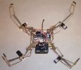
Top Down View Action:
Goes forward.
Also, it does not turn around in place, although it's not impossible.
Could go forward, backward, right or left, maybe someday diagonal.
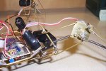
Motor placements:
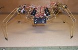
Each leg has a vertical "hip" motor that can rotate the whole leg,
+/- 40 degrees. This motor and leg pivot assembly seems to be tipped
back about 10 degrees (or so).
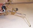
Each leg has a horizontal "knee" motor that can 'lift the lower leg/extend
foot', +/- 30 degrees.
Hard Part:
Setting the front legs so that they lift and
extend, clearing the ground and not dragging while moving in or out.
Harder still: Getting the
Nihon Mini-Motors to "lock" in place while the rest of the 'bot moves.
Noting that the lower strut
is in a different place, looking at the difference between front and rear
legs.
Also, in my opinion for this application, the
Nihon motors run about 75% too fast, a slower gear motor would be preferred.
This is partially solved by running at a reduced voltage, 4.1v from unmodified
cell phone battery.
Figuring out how the "gearmotor hip-pivot assembly"
is angled and rotated in the body.
Measuring the length of all leg parts from the
www.solarbotics.com pictures.
Making a Li-On cell phone battery work, for the
~4.1 volts (& rechargeable, nice).
Making the centering springs work correctly.
(Hi Dave)
Building a reliable "motor-output-shaft spring-assembly"
from the motor to the thigh.
Figuring out the leg movement sequence, this took about 7 days. Still not satisfied on this yet.
Materials:
1/16" brass rod for the foot, upper & lower
struts and underbody bracing. 3/32" brass tubing for the struts pivot
points. 3/32" brass rod for the thigh part of the leg. 0.032"
brass plate for the motor mountings, 1" squares. Jumbo paperclip
wire for the upper "X" bracing (not shown yet).
Eyes:
A device removed form a fully functional auto-focusing lens.
Has IR LED for transmitter and dual sensors at the receiving end.
Looks kinda like the one on Tilden's Spyder. Is black plastic with
two lenses mounted with some blank space in between. The circuit
board is fully functional out to about 15 feet or so. This came from
a table-top projection system, probably surplus. Circuit gives outputs
to two mini-type motors to adjust the lens for focus, etc. These
outputs may be useful in determining what just walked past the 'bot or
movement detection, cats coming in for attack, for instance.
| LEG1 | LEG3 | |
| O | ||
| LEG4 | LEG2 |
| LEG2 | LEG1 | |
| O | ||
| LEG3 | LEG4 |
In Tilden's patent sheet that shows the leg PDC's hooked to the microcore, there's a MUX controlling "GAIT" between legs 3 & 4 (see his patent drawing). How about switching sequences for legs (his legs 3 & 4) 2 & 4 ? What would this do ? Note: doesn't seem to work, not sure what Tilden was doing.
| cycle | 1 | 2 | 3 | 4 | 5 | 6 | 7 | 8 | 9 | 10 | 11 | 12 | 13 | 14 | 15 | 16 | 17 | 18 | 19 | 20 |
| Nv | 1 | 2 | 3 | 4 | ||||||||||||||||
| Leg1 | cw | cw | dn | dn | ccw | ccw | up | up | ||||||||||||
| Leg2 | up | up | ccw | ccw | dn | dn | cw | cw | ||||||||||||
| Leg3 | up | up | ccw | ccw | dn | dn | cw | cw | ||||||||||||
| Leg4 | cw | dn | dn | ccw | ccw | up | up | cw |
| cycle | 3 | 4 | 5 | 6 | 7 | 8 | 9 | 10 | 11 | 12 | 13 | 14 | 15 | 16 | 17 | 18 | 19 | 20 | 1 | 2 |
| Nv | 1 | 2 | 3 | 4 | ||||||||||||||||
| Leg1 | dn | dn | ccw | ccw | up | up | cw | cw | ||||||||||||
| Leg2 | up | up | ccw | ccw | dn | dn | cw | cw | ||||||||||||
| Leg3 | up | up | ccw | ccw | dn | dn | cw | cw | ||||||||||||
| Leg4 | dn | dn | ccw | ccw | up | up | cw | cw |
![]() This
animation is proposed (Run, cat coming ?)
This
animation is proposed (Run, cat coming ?)
![]() This
is also proposed, in a larger Spyder.
This
is also proposed, in a larger Spyder.
![]()
![]() These
two animations don't work so well in application, but they're fun to watch.
These
two animations don't work so well in application, but they're fun to watch.
